We’re not mechanics, or auto electricians at Club 4X4, but we do love everything 4X4’s. And I’d had a set of Ultravision Nitro 180’s for almost a year now, patiently waiting to be installed (after we had taken delivery of our Ford Everest, and fitted a Bullbar).
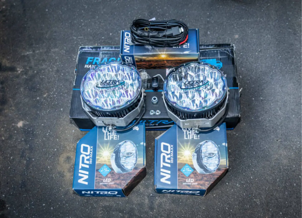
The Ultravision Nitro 180’s, along with the quality wiring loom that comes with every pair
The plan was originally to leave the install to our mates at AE-CO 4X4 (they are currently installing some awesome Rhino 4X4 gear on our Ford Ranger Raptor), but while sick of sitting around at home last week, I decided I’d have a go at installing the lights – I mean how hard could it be?
After a quick trip to Jaycar, I had everything I needed – wire strippers, a soldering iron, solder, wire, heat shrink, a multimeter, as well as a few extras I didn’t!
Now, I’m not going to tell you that what I’ve done is the right way to do things, so if you know better great, but this was my first crack at installing anything electrical in my vehicle without experts on hand to help, so please be respectful with any comments. Shoutout to Wes Whitworth from Unsealed 4X4 for the phone assistance too!
Before you start the install
You’ll need:
- Multimeter or test light
- Fixings to secure the relay to the body of the vehicle
- Fixings to connect Earth
- Wire strippers or a Stanley knife to cut into the existing loom
- Solder and soldering iron to connect the wires
- Heat shrink and/or electrical tape to insulate your new connections and make everything look tidy
- Cable ties to secure the loom neatly
- Socket set or spanners to bolt on the lights
Instructions
Inside the box, there is a really cool but simple wiring diagram which helps make sure you get things right. I found it really useful. There’s also a card with instructions on how to wire the switch up so it works properly too.
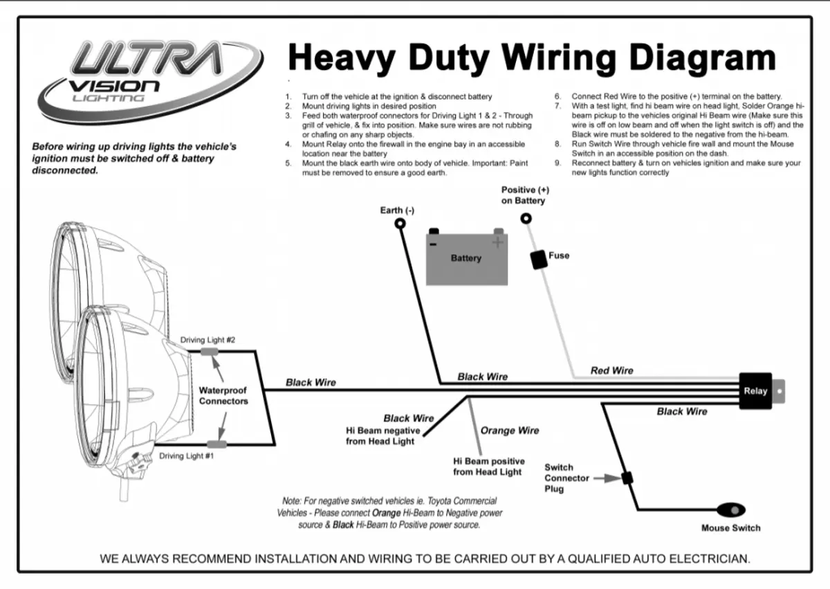
This diagram was really useful and I found I referred to it a number of times during the install.
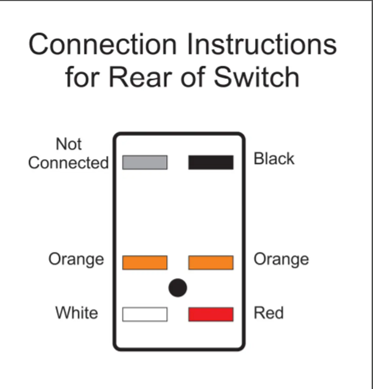
Very simple diagram for the Hi/Lo switch
The wiring harness
One of the great things about the Nitro 180’s is the quality harness that came with them. However, for someone still learning about 12V, it initially looks pretty complex. The Harness not only has connectors for the driving lights themselves, but there is a relay which needs to be bolted to the chassis, and some of the wires off this need to splice into the existing high beam wiring loom. Then, there is a fused cable which connects to the positive terminal of the battery, and another one to earth the circuit. And on top of this, wiring to run through the firewall for the included hi/lo switch to be installed.
I found that the best thing to do was to spread out the loom in the engine bay, and work out how you were going to connect it. I needed to make sure that I could do all of the following with the loom:
- It could reach the driving lights (and I’d fed it through the body where I wanted it to go)
- The relay could mount onto the body of the vehicle
- The red power lead with fuse could reach the battery
- The black power lead could mount onto the body to Earth
- The two wires controlling the relay could reach the back of the headlights so I could splice them in
- The rest of the loom could reach somewhere in the firewall to be fed through into the cabin and reach where I wanted the switch to go
- I could secure the loom and keep it tidy
If you want to attempt this yourself, I’d suggest you lay out the loom in your engine bay and check you can achieve all of the above before you attempt to connect it.
Interestingly, I learned through this process that the relay is really just like a switch for the power, but it turns on or off based on an electrical signal. Rather than draw power from the existing high beam circuit and potentially overload it with the current draw of the driving lights, the relay takes the electrical signal from the high beam, and uses it to turn on the circuit that you’ve just run directly from the battery. When the high beam switch is activated, it opens the relay which allows power to the lights, and when it is switched off, the driving lights turn off.
Once I had laid out the loom, I removed the rubber grommet from the firewall where I intended to run the wiring, and pulled as much as I needed inside. I then checked I had enough slack to tie it around the outside of the engine bay with cable ties, and looked to where I could install the relay. I found a hole on the body in front of the battery, and a screw, and then locked the relay in place first.
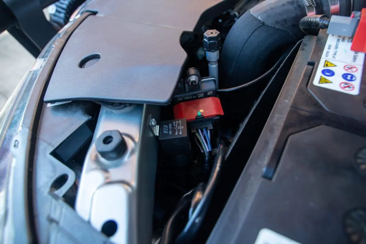
The black box with ‘HID’ written on it is the relay…
Once this was done, I decided to install the lights themselves. When I pulled them out of the box, I got my first glimpse at just how good quality these lights are. The stainless steel brackets were perfectly cut, and very solid, the mounting screws all top quality too (and they’d want to be given the price tag), but everything was highly functional. The best part is that these things are made in Australia – down in Swan Hill in Victoria to be exact!
I got to the slightly fiddly part of reaching through the Bullbar to tighten the nuts on the lights. This was too easy! I was right. It turns out that the bolts have a square coach head on them, which aligns with the mounting bracket to keep it steady. Unfortunately, the square head protrudes a few mm past the bracket – and with a smaller diameter round hole in the bullbar for mounting, there was play in the mounting bolt even when tightened, so the lights could move.
I though about drilling out the bullbar, but that would have meant resealing it so that the thing didn’t rust. So instead I found a washer big enough to squeeze in above the mounting frame which would rasie the bolt enough enough for me to tighten them properly.
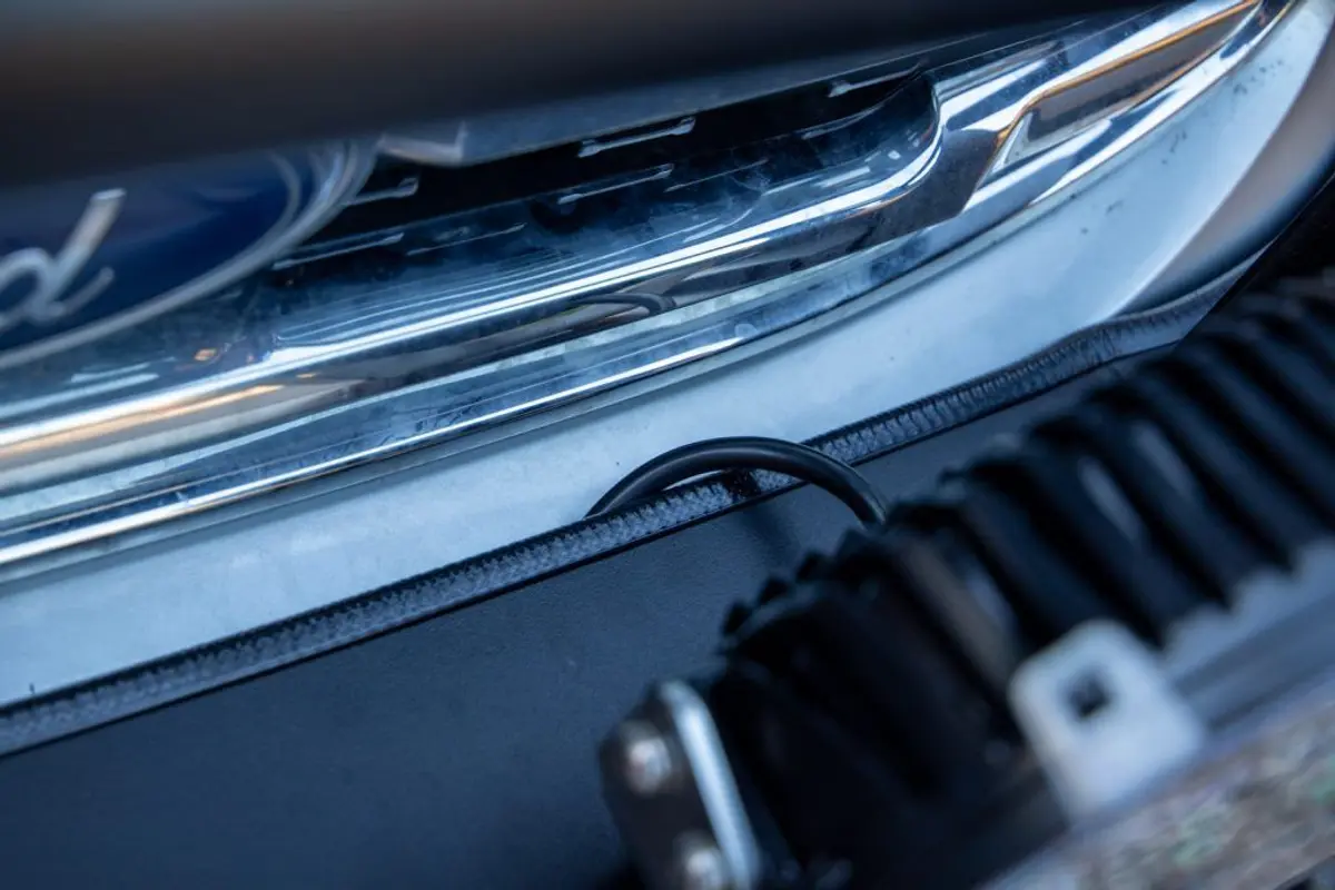
I ran the wiring between the small gap between the bullbar and the front bumper so I didn’t have to go through the grill.
With the lights done, and the loom through the firewall, next up for me was splicing into the headlight loom. Before I did this, I needed to confirm where the headlight hi-beam positive was, and where the negative was to connect the two. I found a very handy Ford fitting guide for the Ranger (which is very similar to the Everest), which had a nice diagram of the wiring. To be sure, I unplugged the lead from the headlight, then put high beam on and checked the wire with the multimeter earthed to the vehicle. I then turned hi-beam off and on a few times and tested just to be sure I got the right one. To find the negative wire for the second trigger wire to connect to, I put the multimeter into the hi-beam wire, turned on hi-beam, and checked the other wires to see which one completed the circuit. The good thing with the Ultravision harness was that the instructions were great, with a very practical wiring diagram.
Once I had explosed the wires I needed, I checked I had the right wire from the Ultravision harness, and then joined and soldered it. When the first was done, I did the same with the second, using heat shrink, and then also electrical tape over the top, before wiring the whole set back together so it looked tidy.
it was now time to connect the switch in the cab, before wiring up the positive terminal to the battery, and the negative to an earth point on the body.
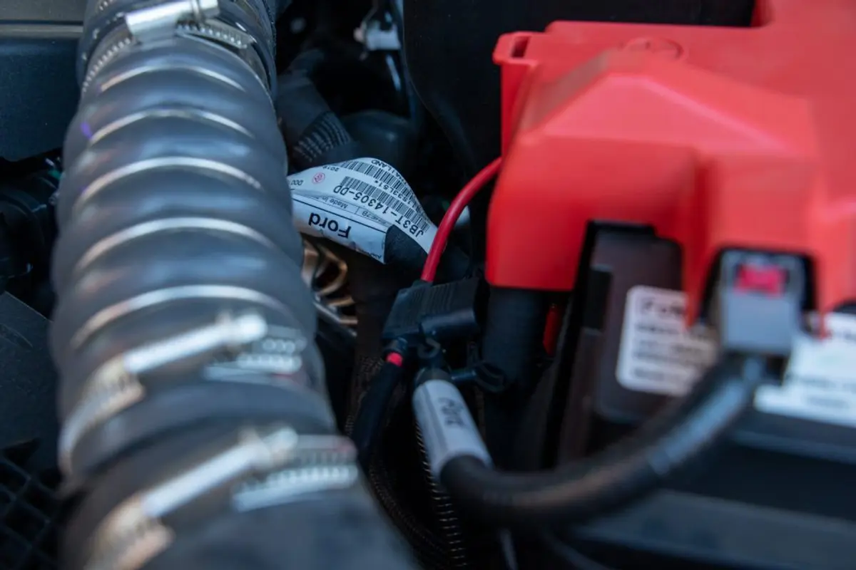
The positive wire connected to the battery (with an inline fuse)
That should be it (almost).
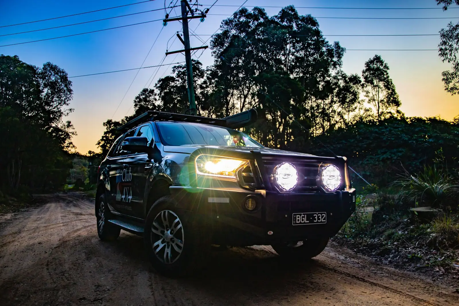
Then the moment of truth – would it work and had I done it right?
Pleasingly, when I turned high beam on with the switch off, nothing happened. And when I changed the switch to low, only the 3 centre LED’s on each light came on. But when I put the switch to full power, the lights lit up the area in front of the driveway, even during the day. Better yet, when I turned high beam off, they turned off, meaning I’d wired them right.
The final step (in my case) was putting the rubber grommet back into the firewall. I disconnected the switch, drilled a hole through the seal, and then fed the harness through it before re-connecting the switch. The trick was to make sure it is tight to keep dust and water out of the cabin.
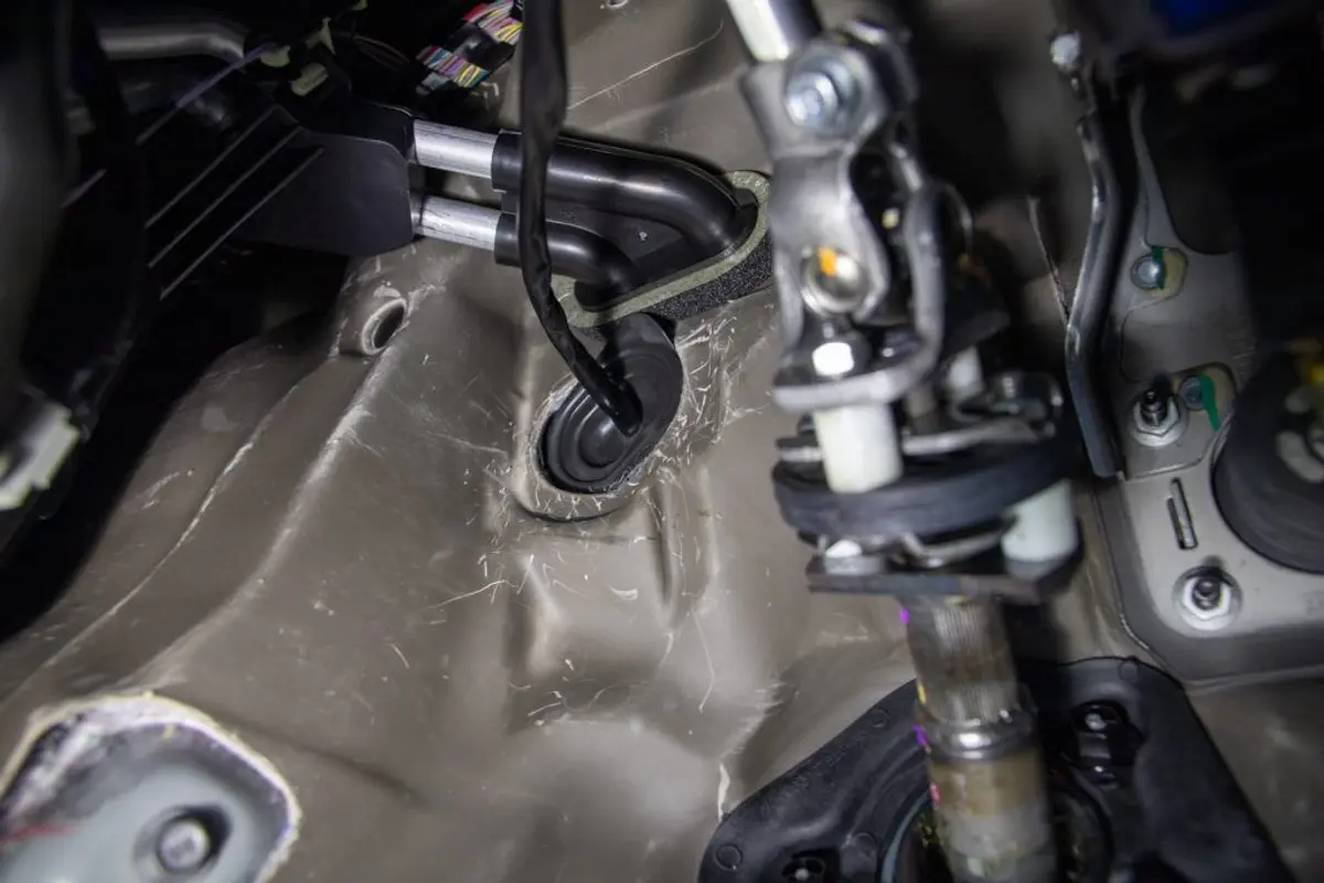
The wiring coming through the firewall. The trick is ensuring a good seal.
Despite the time I’d spent making this happen, I have to say I was really chuffed with the outcome, and the best part is that I know exactly how the lights work and where the wiring runs.
So what are the lights like
Ultravision lights are not cheap, but as I said before, you can see the quality as soon as you get your hands on them. The lighting output didn’t disappoint. I took them driving on back country roads, and I can honestly say that the ‘low’ mode is perfect for everyday driving because the beams supplement the existing high beam very nicely, providing a bit more depth, but not blinding you completely when you pass a reflective road sign.
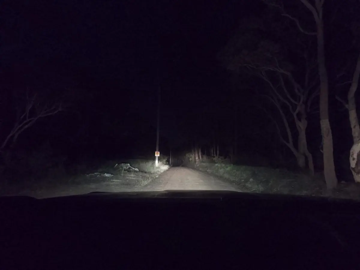
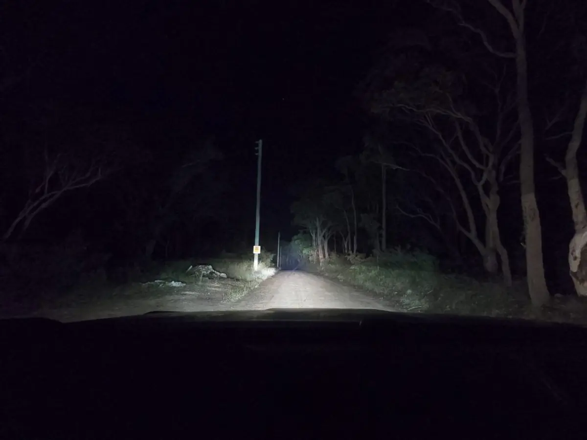
Standard High Beam on the Everest
‘Low’ power mode – Nitro 180’s. It augments standard High Beam brilliantly, without being too much
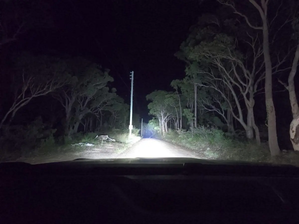
High power. Not only is distance vision incredible, but the peripheral and near vision lighting improvement is fantastic – perfect for night offroading…
Turn on the full power though, and these things light up everything. What was brilliant for a 4WDer though is that not only do they provide great distance, but the combo set we got also really improve close visibility, perfect for night time adventures when you want better near and peripheral vision.
I can’t wait to get these off-road!
Cost: From $849.00 per light
Warranty: 5 Years
Buy direct from www.ultra-vision.com.au
Aiden
Done some DIY at home lately? Or bigger mods? Club 4X4 specialise in insuring the financial investment you’ve made into your 4WD, including all the mods and accessories…